Call (844) 787-4348
That's 844-PURGE-IT


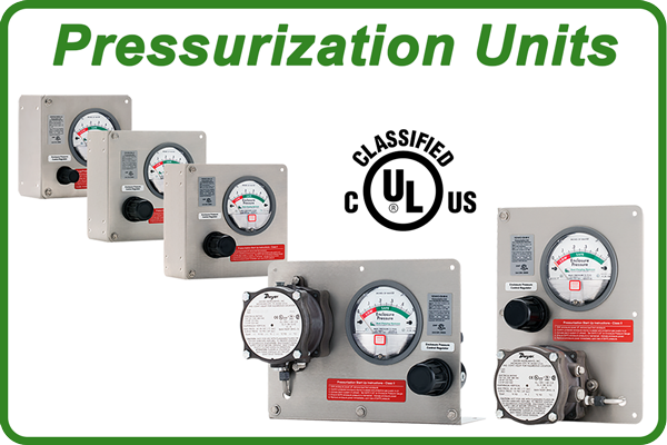
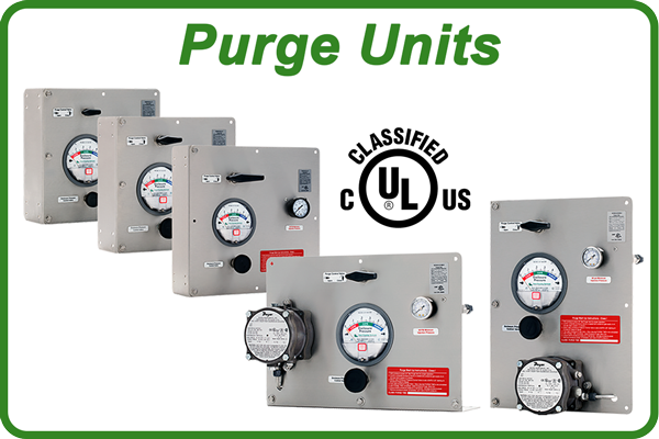
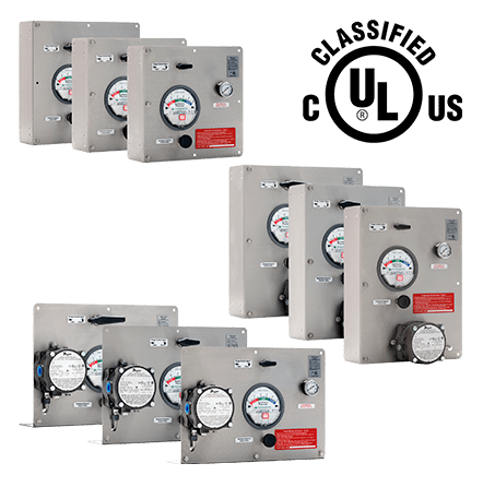
CLASS I & II TYPE Y & Z ENCLOSURE PURGING UNITS
UNIT INSTALLATION
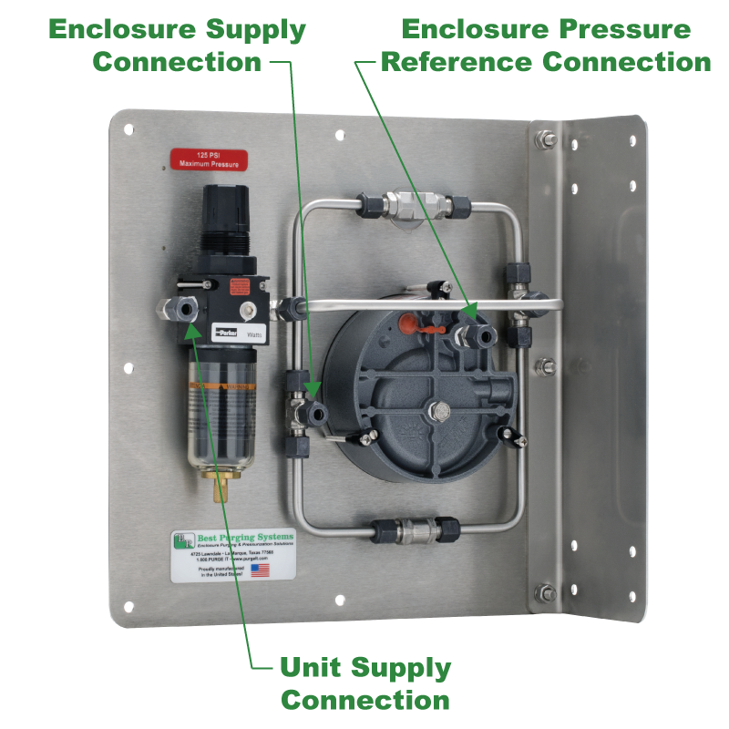
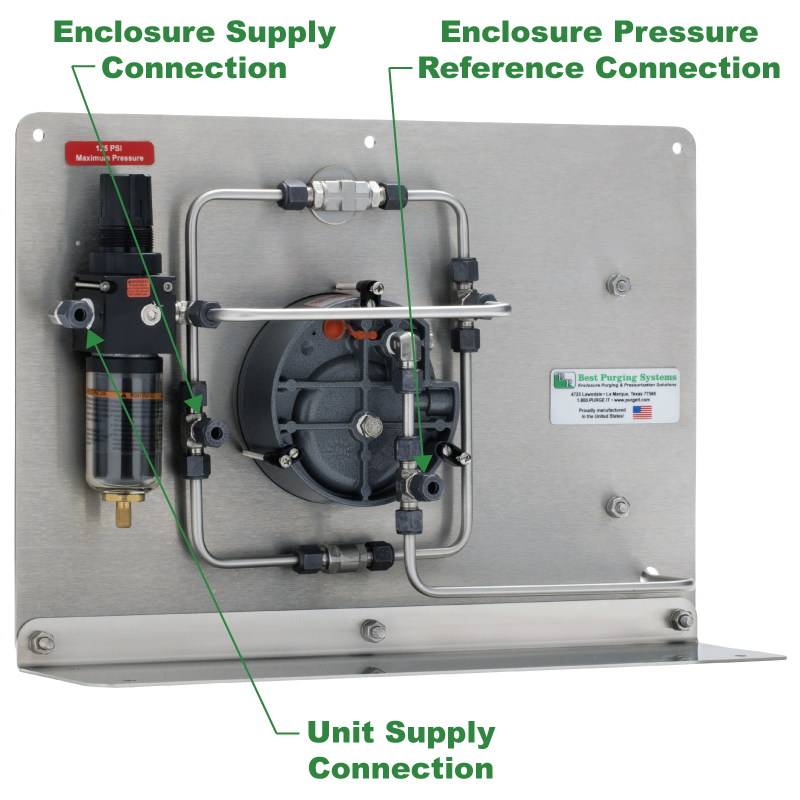
Best Purging Systems Corporation Purge Units feature 3 compression fittings to speed and simplify Unit installation procedures.
We identify the connections to our Purge Units as the enclosure pressure reference connection, the unit supply connection and the enclosure supply connection, as fully described below.
Installation Technicians therefore only require a protective gas source in the immediate vicinity of your protected enclosure and instrument grade tubing along with fittings we offer for your protected enclosure.
For more information, please review our
Installation and Operation Manuals below.
Rely on Best Purging Systems Corporation to provide sensibly designed products that include compression fittings for all unit connections to simplify the installation process!
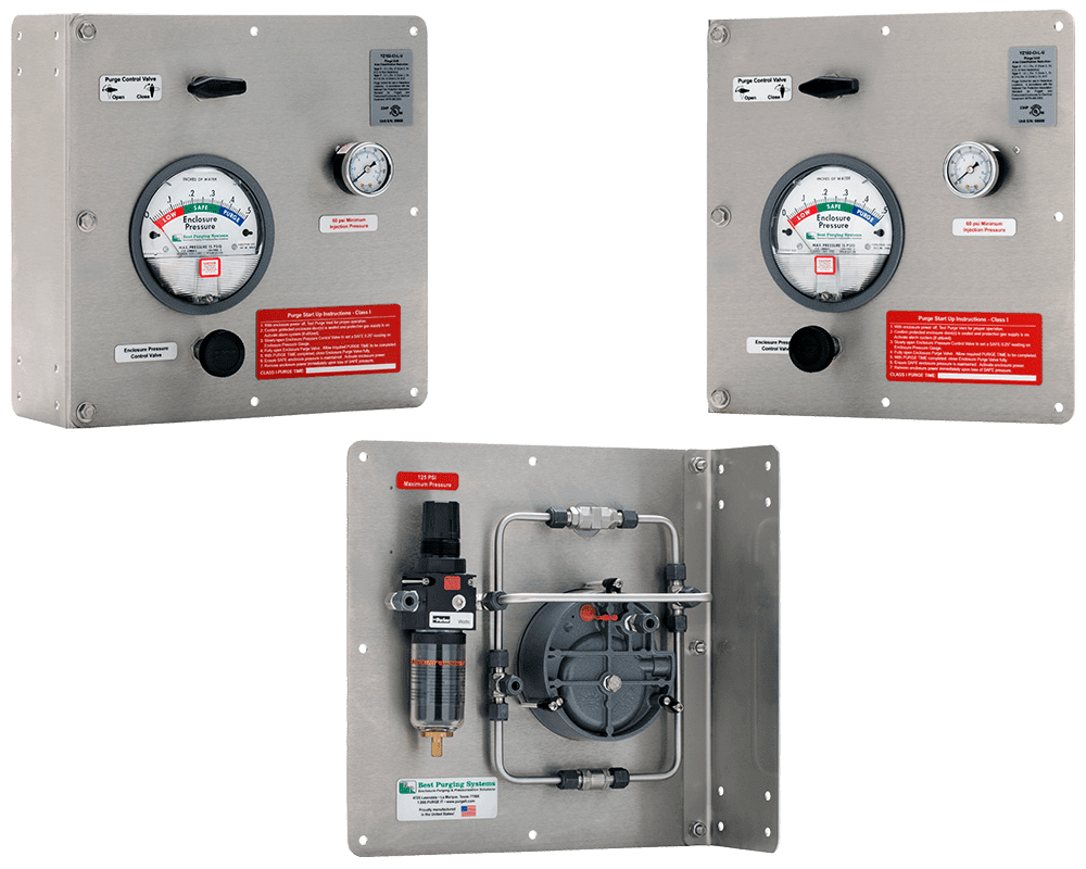
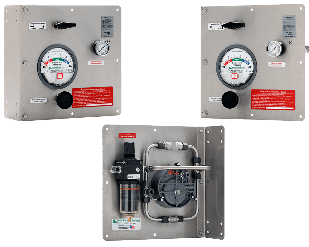
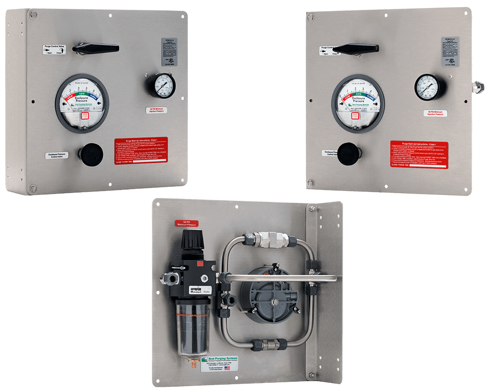
Enclosure Pressure Reference Connection
This connection point is a 1/4″ compression tube fitting, and must be connected directly to the protected enclosure with no valves, restrictions or other devices between the unit and protected enclosure. It originates from the high side of the enclosure pressure gauge and pressure switch if included, and measures pressure within the enclosure as compared to the surrounding atmosphere.
When a Universal Configuration Unit is panel mounted, this connection will not be necessary, but the low side of the enclosure pressure gauge will need to be connected by tubing to a bulkhead fitting that penetrates the protected enclosure to reference the surrounding atmospheric pressure.
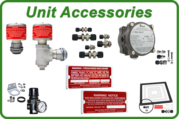
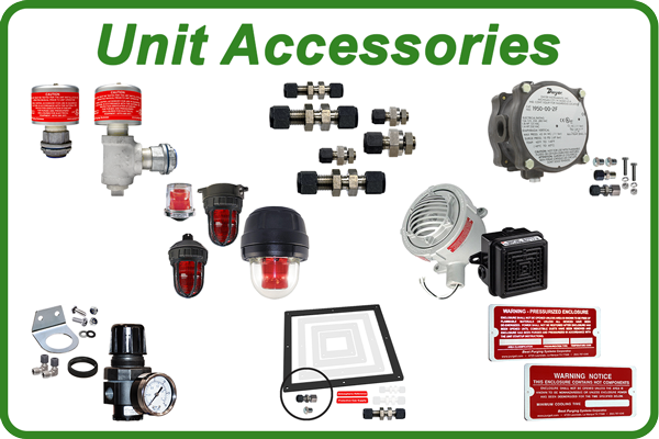
For more information about Universal Unit panel mounting, please contact a Sales Associate, click the Product Accessories Link above, or visit our PDF Library to review our highly detailed Panel Mount Gasket Kit Technical Bulletin.
Unit Supply Connection
This connection point is a 1/4″, 3/8″ or 1/2″ compression tube fitting for Model 102, 103 and 104 Purging Units, respectively. It must be connected directly to a source of clean, dry instrument air or inert gas containing no more than trace amounts of any flammable gases or vapors, with no valves, restrictions or other devices between the unit and the protective gas supply. Pressure must be limited to a maximum of 125 PSI, and the minimum required flow rate will depend upon the unit size selected.
For more information about the required flow rate, please contact a Sales Associate, click the Specifications and Certifications Link above, or visit our PDF Library to review our highly detailed Purging Unit Technical Bulletins.
Enclosure Supply Connection
This connection point is a 1/4″, 3/8″ or 1/2″ compression tube fitting for Model 102, 103 and 104 Purging Units, respectively. It must be connected directly to the protected enclosure with no valves, restrictions or other devices between the unit and the protected enclosure.
It is critical to consider the specific gravity of the potential flammable gases or vapors that may be contained within the protected enclosure. If the gas or vapor is lighter than air and will rise in the enclosure, this connection should enter near a bottom corner of the protected enclosure, and the required purge vent should be located near the opposite top corner to most easily remove any potential flammable gases or vapors. For gas or vapors heavier than air, the opposite technique should be exercised.
Universal Unit Connection Points
Horizontal & Vertical Unit Connection Points
Purge Unit Installation, Operation & Maintenance Manuals
All links below will open in a separate window for your convenience.
Click any Icon to open an On-Line Booklet
with Sharing and Download Options
Click the High or Low Resolution Download Buttons to open Conventional PDF Documents